OfferGet 10% off on Dissertation, Assignments, Essays, Thesis
a) In a De Laval venturi with a subsonic airflow, discuss the velocity, pressure and density changes before the throat, at the throat, and after the throat. Provide a diagram showing velocity and pressure changes along the venturi from the inlet to the outlet. Critically discuss the application of Bernoulli's Equation to the flow and the limitations of the use of the equation. [20 marks]

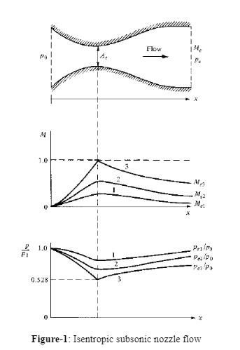
Above relation is called velocity-area equation and is important for isentropic flow in De Laval venturi. This is because the variation of pressure is known by this along with the density of the fluid flow and overall velocity. It is further known that A, ρ, and V are positive quantities. Thus, for the subsonic flow (Ma < 1), the term (1 - Ma2) seems to be positive with dA and dP having the same sign.
At subsonic speed, the density and pressure of the flow decrease before the throat (behave like subsonic nozzles). The throat is a point divided the convergent and divergent portion of the De Laval venturi (Comeaux, 1979). At the throat portion, pressure, velocity, and density vary depend upon the pressure ratio value at the inlet and outlet of the De Laval venturi as shown in the below figure (1). After the throat, the pressure and density of the flow increases (behave like subsonic nozzles).
Bernoulli’s equation is used any time we want to relate pressures and velocities in situations where the flow conditions are close enough to what is assumed in deriving Bernoulli’s equation. You need to be in a flow that is not changing with time and in a regime for which the fluid behaves pretty much like an incompressible fluid without viscosity.
Limitations of the use of Bernoulli’s equation is, if the flow is dominated by viscous stresses (low Reynolds numbers), then Bernoulli’s equation cannot be used. We can still use it for parts of the flow where viscosity isn’t so strong, but inside the boundary layer, for example, we cannot use it. If the flow is highly unsteady, then it cannot be used. In some cases, we might be able to use it, but we have to be careful about how we do it (Dommasch et al, 1967).
b) In the same venturi, if there is an increase in the mass flow rate with an increase in the velocity at the throat increases to Mach 1, initiating a shockwave at the throat, causing the nozzle to be described as 'choked.' The velocity of the nozzle will increase. Critically compare the flow characteristics after the throat in this supersonic scenario, with that in the subsonic scenario in (a) above. Provide a diagram showing velocity and pressure along the venture between inlet and outlet. In particular, discuss the velocity increase downstream and the reasons for the increase. Also, discuss a practical application of the phenomena. [40 marks]
Ans: Consider the converging-diverging nozzle; the entrance of low-velocity fluid is always through the stagnation pressure that is P0. Furthermore, there is the least possibility of flow through the nozzle when Pb = P0. This is mainly because of the fact that flow of the nozzle is based on the pressure difference between the inlet and exit of the nozzle (Etkin, 1982).
Compare the flow characteristics after the throat in a supersonic scenario with a subsonic scenario with pressure difference at nozzle inlet and the exit.
1. If P0 > Pb > PC, there is every possibility of floe remaining subsonic. The mass flow will be further less than the choked flow. In the converging part, the velocity of the fluid increases and reaches to the maximum part of the throat, and there is a loss of velocity in the second part of the nozzle that acts as a diffuser. Thus, it can be said that the pressure decreases and reaches the minimum at the throat with an increase in the diverging section at the converging section.
2. If Pb = PC, throat pressure becomes P* with the possibility of fluid reaching the sonic velocity o the throat. However, a diverging section of the nozzle with act as a diffuser that can further slowdown the flow of fluid to the subsonic velocities. This will also see an increase in the mass flow rate and a decrease in pB but reach the maximum level.
Take P* it can be said that it is the lowest pressure at the throat and the highest velocity in the form of sonic velocity can be achieved through the converging nozzle. There is no documentation of decreasing Pb influencing the fluid flow at the converging part of the nozzle. Thus, there is very possibility of affecting the attributes of the flow especially in the diverging section of the nozzle (Hurt, 1980).
3. If PC > Pb > PE, as the pressure decreases, fluid achieving the sonic velocity continues to achieve supersonic velocity because of the decrease in the pressure. The acceleration of the fluids stops suddenly because of the development of normal shocks between the section of the throat and exit parts. In addition, the remaining part of the nozzle and fluids in it continues to decelerate. The flow is further irreversible at the normal shock and can't be assumed as isentropic. With a decrease in Pb, there is further potential of normal shock moving downstream away from the throat and reaching towards the exit.
If Pb = PE, it means that there will be occurrence of normal shocks at the exit part of the nozzle. The flow can also behave as isentropic because of the supersonic condition, but there is also a possibility of degradation of fluid velocity to the subsonic levels before leaving the nozzle as it crosses the general and normal shocks.
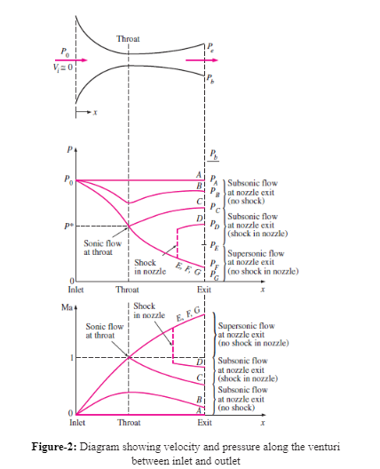
In particular discussion, the velocity increase downstream and the reasons for the increase is, If PE > Pb > 0, supersonic flow occurs in the diverging section and at the nozzle exit the fluid expands to PF with no normal shock forming within the nozzle. Thus, the flow can be assumed as isentropic because of no shocks occurring within or outside the nozzle at Pb = PF (Kuethe et al, 1976).
c) In (b) above, in the choked supersonic De Laval nozzle, the expansion fan at the throat assists the velocity to increase, and pressure, temperature and density to decrease, which is a typical effect of an expansion fan. Critically discuss the effect of an expansion fan compared to a normal shockwave, discussing the different actions of the two results.
Ans: The below figure suggests that each number and variation of the pressure exists below the critical condition. The decrease in the pressure in the convergent part of the duct leads to an increase in the match number. This also leads to many numbers reaching to unity at the convergent section.
Additionally, fluid continues to reach to the initial and internal part of the divergent portion which further leads to an increase in the match number and a systematic decrease in the pressure (Shevell and Richard, 1983).
However, if the fluid keeps expanding and reaching to the rest of the duct, there is every possibility of pressure reaching to the exist that will be much lower than the exit pressure as a whole. After the initial expansion, there is also a possibility of normal shocks for increasing the pressure and decreasing the Mach number. Thus, the remaining part o the duct helps in acting as a diffuser for increasing the pressure and flow to the exit direction simply and easily.
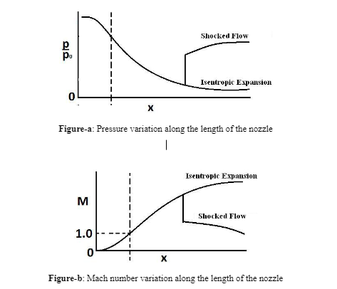
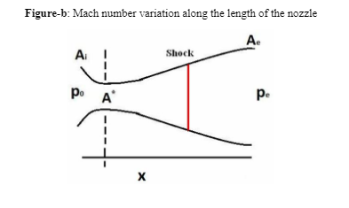
It can be further said that because of the normal shock moving towards the exit of the duct, the divergent part acting as nozzle decreases in the exit pressure. Furthermore, normal shocks stay at the exit of the divergent duct having a specific value for the exit pressure. The decrease in the exit pressure and change in the shock pattern is produced at the edge of the duct that leads to a rise in the pressure for attaining the exit pressure conditions (Smith, 1992).
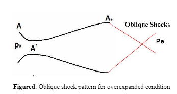
It can be further said that the exit pressure condition leads to the generation of isentropic flow that is created inside the duct. This flow is often lower than the exit pressure and has to pass through the shock of attaining the pressure of the exit pressure through the non-isentropic process. This condition is often known as “overexpanded nozzle.” Another phenomenon happens in the form of a decrease in the exit pressure because of the decrease in the strength of shock. The specific value of existing pressure make the flow isentropic for the duct, and the fluid pressure becomes similar to the exit pressure (Talay, 1975). In such case, the divergent and convergent parts of the duct start acting as nozzle along with expanding smoothly. This is why the duct is known as convergent-divergent (C-D) nozzle. The same has been explained in figure (a) and (b). It is further found that any decrease in the exit pressure after reaching the isentropic condition might lead to higher degree of fluid pressure at the exit compared to the ambient pressure.
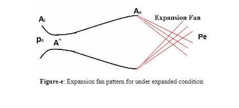
It can be further said that the decrease in the pressure for reaching towards the ambient condition is because of the expansion fan getting originated from the edge of the nozzle. This condition is known as ‘under expanded nozzle flow', that has been shown in figure (e).
a) Critically discuss the theory related to circulation as related to the Magnus effect, including the horseshoe vortex field around an aerofoil, and discuss the relevance of the Kutta Joukowski theorem to the integral field theory of lift. [40 marks]
Answer:-Circulation is the line integral surrounding a closed curve of the velocity field. It is usually shown by symbol Γ (Greek uppercase gamma) (Clarke, 2007). V is the fluid velocity on a tiny part of a predefined curve, while dl as a vector represents the variance length of the tiny part, the impact of that variance length to circulation is dΓ:
dΓ=Vdl=Vdlcosθ
Here θ is the angle existing amid vectors V and dl.
Line integral is the circulation that surrounds the closed curve C
Γ=∮V·dl
The magnitudes of circulation are square in length, divided by time; L2⋅T−1. It is equal to velocity time’s length (Gablehouse, 2015).
Kutta–Joukowski theorem:
The lift per unit span (L') working on an object in a two-dimensional inviscid flow area could be shown as the multiple of the circulation Γ around the object, the fluid density ρ, and the object’s velocity with respect to the free-stream V. Therefore,
L′=ρVT
Hence, Kutta–Joukowski theorem is explained.
The above equation is applicable across airfoils, as here the generation of circulation is undertaken with the help of airfoil action, and across revolving bodies, undergoing the effect of Magnus, as here the circulation is prompted in a mechanical manner (Clarke, 2007).
Circulation is utilized to compute forces on bodies such as the airfoil. In the condition where the airfoil generates lift, there occurs finite circulation across the airfoil. This is associated with the boundary layer’s velocity. At the exterior of boundary layer the vorticity remains nil, and hence, the circulation remains constant across each circuit, irrespective of circuit’s circumference length.
Association with vorticity
Circulation could be associated to vorticity:
ω=∇×V
According to Stokes' theorem:
Γ=∮∂sV·dl=∫∫sω·dS (actually its cyclic integral suffix ∂s, integral suffix s)
On the condition that the path of integration is an enclosure (shown by "∂") of a closed plane S, and not simply a closed loop. Hence, vorticity is the circulation per unit area, taken about a minuscule circle. Therefore, circulation is the flux of vorticity.
HORSESHOE VORTEX:
This is a simpler version of the wing’s vortex structure. Here the wing vorticity is taken as an exemplary by a looped vortex of fixed movement, moving with the wing, and dual straggling wingtip vortices, thereby possessing a form which is a bit like a horseshoe. The opening vortex is removed as the wing starts its journey via the fluid, and this disperses due to the viscosity’s action. The same occurs to the remaining vortices which are let behind the airplane.
The sprawling wingtip vortices have an effect on the constituent of the downwash, and this generates prompted drag (Clarke, 2007).
The model of horseshoe vortex is impractical as here there is the implication of unchanging circulation (and therefore, with regards to the Kutta–Joukowski theorem, uniform lift) at wingspan’s entire areas. Contrarily, the lifting-line theory is more practical as here the strength of the vortex alters across the wingspan, and the lowering in vortex strength is removed as vortex sheet across the entire sprawling corner, and not just a solitary trail at the wing-tips. The less complicated type of horseshoe vortex is utilized with a minimized operative wingspan yet; the same mid-plane circulation supplies a suitable example for the flows incurred at a distance from the air carrier.
Q2 (B):- Critically discuss the Kutta condition as it relates to the starting vortex generated at the sharp trailing edge of a conventional aerofoil, and the importance of that trailing edge. [30 marks]
KUTTA CONDITION:
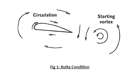
The application of the steady-state Kutta state for a flat surface or a Joukowski airfoil (having cusped trailing corner) was previously discussed in our earlier work [7]. Usually, this state is same as enforcing an unchanging spot at the trailing corner in the mapped cylinder surface (Clarke, 2007). Nevertheless, Xia & Mohseni [8] later showed that a point of stagnation usually remains absent at the trailing corner of an unsteady flat plate that has rotary motion. To address this difficulty, they further proposed a modified Kutta condition which relaxes the trailing edge point from completely motionless to just motionless in the tangential direction of the surface in the cylinder plane. They have shown that this modified Kutta condition is consistent with the physical definition of the classical Kutta circumstance that flow around the sharp edge should be prevented in a reference frame that is fixed to the flat plate. This condition can be generalized in the bodily sphere (the plane of the flat plate or airfoil) as
ug · n = 0,
Where ug denotes the de-singularized flow velocity at the trailing corner, and n signifies the vector at a ninety degree to the trailing-edge tangential vector (n · t = 0)
The unsteady Kutta condition (Eq. 1) have been shown to yield promising results in estimating vortex-sheet formation at cusped trailing edges, yet, it was only validated for the situation where a flat surface or a Joukowski airfoil could be shaped to a circle. For a general airfoil, solving Eq. 1 might be challenging because of possible finite-angle trailing edge. As, the two bound vortex sheets at a definite angle trailing corner are at a certain angle to each other, which is different from the case of a plane surface or a cursed airfoil where the two intertwined vortex sheets share the same tangent (Charles, 2015). According to Stevens and Hobart (2009), this inconsistency of the direction of flow at the trailing edge creates an ambiguity in deciding the angle of the streamline emanating from the sprawling corner, especially for unstable cases. In this study, we propose that the angle of the sprawling corner vortex sheet should be decided in a momentum conservation sense. As a result, the angle of the resultant vortex sheet can be decided by
γ2 sin ∆θ2 + γ1 sin ∆θ1 = 0 with ∆θ1 · ∆θ2 ≥ 0,
And
∆θ1 + ∆θ2 = ∆θ0, (3)
Where ∆θ0 is the finite angle of trailing corner. The unsteady Kutta state for an airfoil is validated through the simulation of a NACA 0012 airfoil with a combination of heaving and pitching motion.
IMPORTANCE OF TRAILING EDGE:
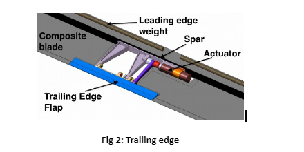
The trailing edge of a flowing plane like a wing is the hindmost corner. Here the existing separation in the airflow re-joins at the leading edge. [1] Necessary flight control exteriors are fixed here to transmit the air flow and apply a regulatory power by altering its impetus. These types of control planes comprise of ailerons on the wings for roll control, elevators on the tailplane monitoring pitch and the helm on the fin supervisory yaw. Ailerons and elevators could be joined as elevons on a tailless airplane.
There might be some other equipment and planes which could be fixed to the trailing edge of the airplane’s wing or on its control planes (Anderson, 2007). These comprise of:
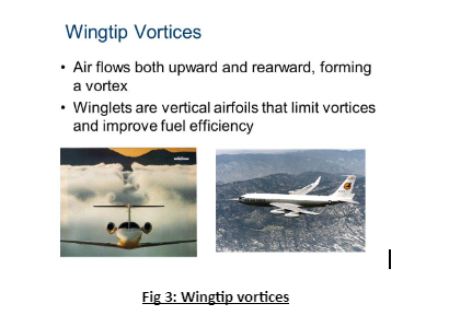
Wingtip vortices are spherical configurations of spinning air trailing behind a wing as the lift is generated (Neilson, 2004). A single wingtip vortex stays behind the tip of every individual wing. Wingtip vortices are occasionally called trailing or lift-induced vortices. The reason is that they even exist at other places and not just at the tips of wings. In fact, the vorticity is trailed at any section on the wing that has the variable span-wise lift (backed by the lifting-line theory); Later on, it rolls into huge vortices close to the wingtip, at flap devices’ corners, or even when the wing platform alters abruptly. These are connected with prompted drag, the conveying of downwash, and are an essential result of generating of three-dimensional lift. According to Stevens and Hobart (2009), vigilant choosing of wing geometry (specifically, aspect ratio), along with cruise states, are design and operative techniques to lower prompted drag. These vortices are the essential constituents of wake turbulence. The water could freeze or condense in the vertices core depending on the wing loading and geometry of the airplane or the humidity in the atmosphere. This would make the vortices observable.
It is the job of the pilot to manipulate the controls to attain and sustain meticulous aerodynamic flying. [1] Any alteration in the flight control structure is conveyed mechanically to the roto (Clarke, 2007). This generates aerodynamic pressures on the rotor blades making the air carrier to move in a specific fashion. The pilot controls all the movements whether tilting forward or backward (pitching) or rolling sideways by altering the attack’s angle of the major rotor blades cyclically in the course of the rotation. This creates diverse quantities of lifts (force) at varying places in the cycle. The pilot could decrease or increase the overall lift by controlling and altering the angle of attack. This is undertaken for entire blades by equivalent quantities at the exact duration. The result is control of acceleration, de-acceleration, descent, and ascent. Helicopters usually come with triple flight control inputs. They are—anti-torque pedals, collective layer, and the cyclic stick.[2] Contingent to the intricacy of the machine, the cyclic and collective could be joint via a mixing element, a motorized or hydraulic apparatus that syndicates the contributions from both and later transmits through the "mixed" contribution to the control planes in order to attain the preferred outcome (Anderson, 2007). The physical throttle could even be regarded a flight control as it is required to control propeller speed on tinier airplanes devoid of governors. The pilots get assistance from governors in controlling the shared pitch on the air carrier's major rotors, to maintain balance and stability during flight.
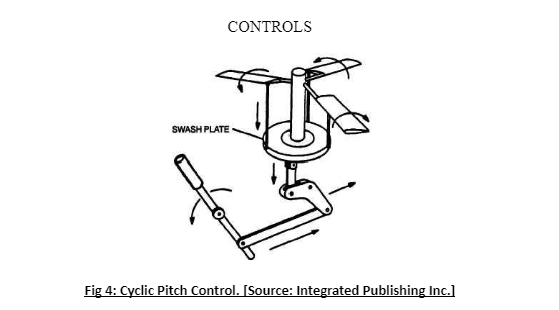
The cyclic control, generally known as a cyclic stick (or cyclic), looks same on the majority of helicopters. The cyclic could normally be found between the legs of the pilot. In certain helicopters, like Robinson R22, the cyclic is a pivotal pillar which could be manipulated by any of the pilots. The name cyclic is given as it alters the pitch slant of the rotor blades cyclically. In other words, the feathering angle or pitch of the rotor blades alters. This alteration is dependent on position due to the rotation. Hence, according to Clarke (2007), entire blades possess similar occurrence at the exact location of the cycle. This alteration in cyclic terrain produces an alteration on the angle of attack, and thereby there is a change in the lift produced by a solitary edge as it revolves about the propeller disk. Consequently, the blades move down or up in sequence, and this movement is dependent on the alterations in the lift which affects every single blade. The propeller disk is tilted in a specific track that propels the plane to move in that particular direction (Anderson, 2007). Hence, if the pilot thrusts in the forward direction, then the rotor generates a simultaneous thrust vector in the same direction. Similarly, if this push is towards the left, the tilt of the rotor disk lies to the left and generates a thrust in the left direction. This causes the aircraft to move towards the front in a hover or to roll into a left turn during forwarding flight, in the same manner of a fixed wing air carrier. There is, however, always a delay amid the point in the rotation in any rotor system. It occurs when the controls present a variation in terrain and the area where the anticipated variation in the rotor blade's voyage transpires. This variance is instigated by period lag which is often misunderstood with gyroscopic precession (Clarke & Carson, 2007). A propeller is an oscillatory structure that follows the rules that manage tremor and is dependent on the rotor system.
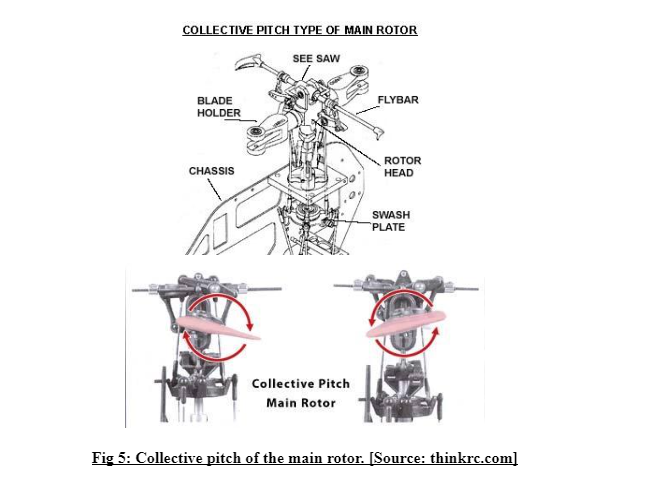
The collective lever or collective pitch control could be found to the left of pilot's seat. It has a modifiable friction control to avert unintentional movement. The job of the collective is to change the pitch angle of entire prominent rotor blades in a collective manner (instantly) and without being dependent on their location. Hence, if an input is made collectively then entire blades alter alike, and consequently, the plane upsurges or falls in its overall lift gained from the rotor. Scaife (2011) states that in flat flight this might induce a descent or climb, whereas with the aircraft pitched forward an augmentation in overall lift might generate a speeding up along with specific rise up. The collective terrain controller in a Boeing CH-47 Chinook is known as thrust control. However, its purpose is the same save for controlling dual rotor systems and using distinction collective pitch.
Anti-torque pedals
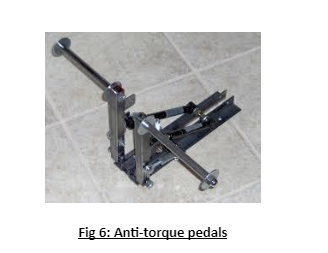
Clarke and Carswell (2007) state that the anti-torque levers are situated in the location that houses the controls levers in an aircraft, and its purpose is also the same, that is to control the direction of the aircraft’s nose. The application of pedal in a specific direction alters the pitch of tail propeller blade, augments or reduces tail propeller thrust and makes the nose yaw in the direction of the enforced lever (Neilson, 2004).
The designs of helicopter propellers are made such that they function at a particular speed of rotation. The power of the engine is controlled by the throttle, and this throttle is joined with a rotor by a transmission. The setting of throttle should generate adequate engine power to maintain the rotor speed to a specific limit and where enough lift is produced by the rotor for flight (Scaife, 2011). Numerous helicopters have solitary or twin motorbike-type spiral hold attached to the shared controller (spin is reverse of a motorbike regulator) for throttle control, whereas certain multiple-engine planes work on power controls. Pilots in several piston engine-powered helicopters employ the throttle to sustain the speed of the rotor (Charles, 2015). Turbine engine helicopters, along with few piston air crafts, utilize governors or certain electro-mechanical controller structures to preserve the speed of the rotor and release the pilot of regular accountability for that job (Stevens & Hobart, 2009).
Main Rotor System
Root: The innermost end of the blade. Here the propellers get connected to the blade holds.
Blade Grips: Enormous fastening sockets. Here the propeller blade gets connected to the hub.
Hub: It sits on the mast. It attaches the rotor blades to the controller tubes.
Mast: Spinning shaft from the communication that joins the rotor blades with the plane.
Control Tubes: Push \ Pull tubes that alters the arena of the rotor blades.
Pitch Change Horn: The framework that transforms controller tube movement to blade pitch (Anderson, 2007).
Pitch: augmented or diminished position of the rotor blades to elevate, gravitate, or alter the direction of the rotors plunge force.
The collective control could direct the swash plate assembly to alter the slant of both blades simultaneously. This alteration could augment or minimize the lift that is supplied to the vehicle from the main rotor. Hence, this allows the helicopter to rise or go down in altitude (Anderson, 2007).
The cyclic control directs the swash plate assembly to alter the slant of the blades independently as they rotate. This permits the plane to go in any direction around a 360-degree circle, containing rightward direction, the leftward direction, front or even back (Neilson, 2004).
There are two plates in the swash plate assembly -- the stationary and the revolving swash plate (Stevens & Hobart, 2009).
The spinning swash plate spins with the drive shaft (green) and the rotor's blades (grey) owing to the links (purple) which join the spinning plate to the drive shaft.
The pitch controlling bars (orange) permit the spinning swash plate to alter the field of the rotor blades.
The controller rods (yellow) fixed to the stationary swashplate alters the slant of the stationary swashplate (Anderson, 2007).
The stationary plate's controller sticks get influenced by the pilot's contribution to the collective and cyclic controls. The stationary and spinning swash plates are joined with a set of bearings amid the twin plates. These bearings permit the spinning swash plate to rotate directly above the stationary swashplate (Stevens & Hobart, 2009).
Collective: The upwards and downwards control. It positions a collective controller contribution into the rotor structure that is that the collective positions either "all up," or "all down" controller inputs in at a single instant via the swash plate. The operating mechanism comprises of a stick situated on left side of the seat. This is known as the collective pitch control. A pilot can use it easily by his or her left hand (Neilson, 2004).
Cyclic: The leftward and rightward, frontward and aft control. It positions a single controller input into the rotor structure at an instance via the swash plate. This is called the "Stick" too. Its position is at the center of the cockpit’s floor, and lies amid the legs of the pilots. The pilot can easily operate it through his or her right hand (Gablehouse, 2015).
Pedals: Similar to the rudder pedals found on airplanes, these are different.
There is an absence of real rudder on a solitary rotor helicopter. An anti-torque rotor (also referred to as a tail rotor) fulfills this absence. The anti-torque rotor is accountable for controlling of directions at a hover, and plane trim in frontward flying. The pilots operate the gearshifts through their feet in the same fashion as an airplane rudder pedals (Anderson, 2007). These pedals are also present in tandem rotor helicopters. However, they maneuver both chief rotor systems for guiding control at a drift.
There should not be any problems with the helicopters rotor system unless faced with one of two challenges. Either there was a movement by the aircraft in any given direction, or some wind was introduced in the primary rotor structure. If any of these events transpire, then there would be instability in the rotor system, and the ensuing smash must surely result in casualties (Anderson, 2007).
If the same state occurs throughout the rotor arc’s perimeter, then there is an equality among everything, and the system experiences a balance. The system would experience instability if there were the difference in the speed of the wind from any angle. Hence, it would start rotating. This could be noted in the example of a forward flight (Stevens & Hobart, 2009).
For example, if the movement of the blade towards the frontward end of the plane is 100 MPH while that of the blade towards the posterior of the airliner is 100 MPH in the opposite direction, then this would not impact the balance of the aircraft if it is stationary or has no wind condition. The reason here is that the aircraft is undergoing 100 MPH of wind from all four directions, and this helps in maintaining balance. However, if the aircraft surges forward, then the balance starts to suffer. At this stage, the rotor blade experiences 110 MPH of wind speed, while the rearward experiences just 90 MPH of wind speed (Cumpsty, 2003).
This sort of situation paves the way for unbalanced condition. Here the proceeding blade undergoing extra lift tries to climb, whereas the withdrawing blade undergoes lesser lift and tries to drop. This sort of situation gives rise to the term "Dis-Symmetry of lift." The lift is asymmetrical about the complete rotor structure (Stevens & Hobart, 2009).
We recompense by permitting the rotor to fold. By permitting the proceeding blade to fold upwards, and the withdrawing blade to fold downwards, it alters the slant of incidence on both propeller blades. This brings the whole rotor structure into equilibriums, permitting the blades to fold on pivots (Articulated rotor system). A different method is to make the entire middle thump up and downwards about an inner bearing known as trunnion (Semi-rigid rotor structure). There could not be any complete compensation for dis-symmetry of lift by utilizing blade flapping. At a time when the air carrier has gained a specific airspeed, and there has been enough flapping by the rotor, the "Retreating blade stall" could be felt. In retreating blade stall, the withdrawing blade could not recompense for the lift’s dis-symmetry, and the exterior parts of the blade would "Stall." Solitary rotor helicopters do not normally want to alter the overall design on their machines due to the involvement of added expenditures for smaller airspeed payoff. Many have accepted their air carrier’s slower airspeeds, at smaller expenses and lesser upkeep.
According to Stevens and Hobart (2009), the central rotor hub, which acts as a connection for the rotor's drive shaft and blades must remain excessively sturdy and extremely adaptable. The swash platter assembly is the constituent that supplies the adjustability.
Answer: The A380 Airbus has a wide body and is a double deck with four engines being European manufactured. Since, it is the largest passenger airline in the world, airports across the world have taken significant steps in extending their facilities to accommodate the airliner. The reason behind its introduction was to challenge the monopoly of Boeing in the aircraft market. There is a joystick that is located at the side of the console of the pilot on the right-hand side and is mainly found in aircrafts equipped with wire control systems. On the other hand, the throttle control is usually found at the left side of the pilot. This also means that the control is mainly based on using one hand at the time rather than using both the hands as practically it is not possible (Kuethe and Chow, 1998).
The control of pilot and co-pilot is mechanically connected that offers a great degree of control to both the pilots. The computer system of the plane offers multiple inputs to the pilot along with offering them the facility of pressing “priority button” in order to lock the inputs from the other side as and when required. There is also a control wheel that is known as Yoke for piloting the wing aircraft. The major purpose of the yoke is to manage the altitude of the plane during the pitching and to roll. It needs to be mentioned that the pulling of yoke leads to the rise of the aircraft nose and vice versa. In addition, when the yoke is pulled towards the right, the place sways in the right direction and vice versa (Anderson, 2001).
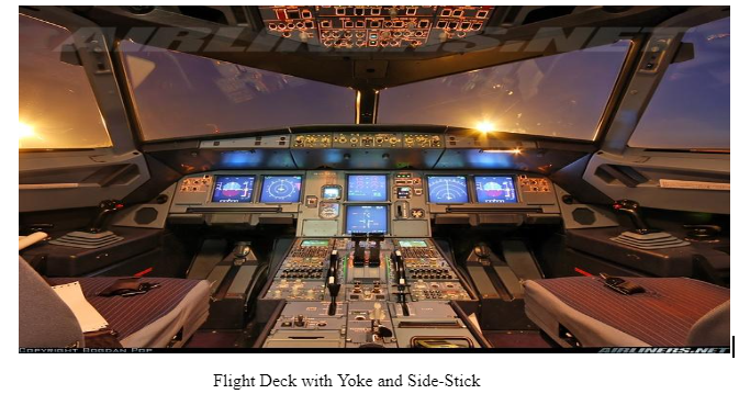
Reference: Stack Exchange (2017) Side Stick Vs. Yoke. [Online] Available at https://aviation.stackexchange.com/questions/23388/sidestick-vs-yoke. [Accessed December 17, 2017]
Advantages and disadvantages
There is no doubt that center sticks are further used to control the inputs along with the management of the g-forces that are used in the sport, military, and other aircrafts. However, the sensitivity of yoke is quite low because of the high range of motions and thus offering better degree of visual aid to the pilots. Usually, yokes are connected and when pulled offer instant indication to the pilot using the control input. Yokes take more place that side sticks and may hinder the visibility of other objects. In this regard, the usefulness of side stocks is quite high as they take little space along with obstructing the visibility of other objects in the least possible manner (Talay, 1975).This makes them cockpit friendly allowing for a better degree of maintenance. However, the yoke can be used by either hand and might be useful in manipulating wide arrays of control in the cockpit. These advantages are further shared by the center stick. Some of the key factors are in the form of:
Human factors:
•Reduction in the awareness towards varied situations
•Increase in the demand for better degree of monitoring
•Overload in regards to cognitive
•There is also excessive trust or complacency
•overdependence on the automatic control
•Lack of manual practices
•Requirements for new training and procedures
•Reduction in the situal control because of the lack of awareness
•Increase in the management workload
•Reduction in the level of motivation and job satisfaction
•Increased chances of human errors
Yokes have certain attributes in the form of:
The sensitivity level is quite low compared to the side sticks because of the varied degree of motions
They usually require great deal of space that affects the visibility of other tools and objects
They can be used easily with any hand and thus offer flexibility
They are often used in wide arrays of aircrafts and are easily managed
Pilot and co-pilot can easily integrate their yoke mechanically that is more than impossible in the case of side stick
The yoke is also beneficial regarding offering visual indication to the pilot when the control input is given
Sidesticks have certain attributes in the form of:
The sensitivity level of side strick is quite high but offer little range of motions and movements. They are also marked by rapid movements.
They usually take little space, and thus visibility of other tools and objects is quite high
When there is a two-person cockpit, the visual assistance is usually quite low when the control input is applied. This can be assumed as a major limitation
The management and operation is basically through one hand only
There is a need for FBW system regarding the operations
Answer:-Fly-by-Wire (FBW) can be defined as generally accepted terms for flight control system using computers systems to process the control inputs being made by the pilots or co-pilots. They are also used to send electrical signals and thus replacing the mechanical linkage. This is often helpful in assisting pilots to not move the control surfaces directly, and inputs are easily read by the computers determining the movement of the control surfaces. This also ensures that pilots achieve what is important in accordance with the available Flight Control Laws (Etkin, 1982).
The military aircraft design first recognised the importance of improved reliability, weight control, effective control, damage control for maintaining and managing the movement of aircrafts. The first flight incorporating all these necessary tools was F-16 in 1973 by replacing the direct mechanical inputs and assisted operations. The usefulness of FBW is also in the form of improving the agility of aircrafts and helping in dealing with wide arrays of issues in the form of lack of control, deflection issues, and weight issues. It also facilitates the flight envelope protection and thus enhancing the level of safety (Crouch, 1983).
Control Laws
The FCCs at the center of an FCS are often supported and programmed with some control laws that also help in governing the feedback appropriately. They are commonly named after the feedback parameter, and some of the most common forms of feedback are in the form of:
Pitch Channel: vertical load factor ‘g,’ pitch rate ‘q,’ pitch angle ‘θ’, the angle of attack ‘α.’
Roll Channel: bank angle ‘f,’ roll rate ‘p.’
Yaw Channel: yaw rate ‘r,’ sideslip angle ‘b,’ rate of change of sideslip angle ‘b with a dot over it’ verbalised as ‘beta dot’).
It can be said that the command’ that is also the desirable capability usually at the high speeds suggest that for specific speeds and control force, there is some degree of “g” irrespective of the prevailing airspeed. At the same time, there is same degree of pitch rate for the control column irrespective of the prevailing speed (Berry, 2002).
The FCC further offers a direct path regarding balancing the requirement for communication among pilots and maintaining the same degree of context. This is offered via the proportional line or feedforward gain through a parallel circuit producing a control surface command until there is a feedback signal that is equal to the initial and original command signal of the pilot (Davies, 1994). It is further important for engineers to fine-tune the integrator in order to prevent excessive lag. It needs to be mentioned that too much of integration might lead to a gain of “K” that would further lead to an excessive lag in the aircraft.
This is why there is proportional plus integral being found in majority o the flight designs including the likes of Airbus and Boeings. It needs to be mentioned that the g command is helpful in offering altitude hold that is similar to the feature of control wheel steering in the case of autopilot. The system further holds the new attitude whenever, there is a change in the control pressure, pitch, and altitude. The aircrafts usually fly with moderate control forces and precise control of the altitude. It is also helpful in changing the speed without re-trimming the existing settings. The same principle applies to the thrust and configuration changes. The usefulness of auto trim is further in the form of offering neural speed stability and helping in better control of the flight. However, lack of this is also acceptable in FBW flights. However, majority o the FBW types and other flights retain the conventional trim level (Gibbs, 2003).
The control law that integrates the g and pitch rate is C*. At low speeds, there is an application of C* and at high speed, there is an application of g. The change is always transparent and is often useful in signifying the increase and decrease in the speed of the flights. There is also a use of trim switches that is ummed with the real speed in the FDD feedback offering the feeling of conventional control force to the pilot whenever there is a speed change (Smith, 1992).
After looking into the details of the specific phases of flights, there is further aid by FBW regarding allowing designers to optimise the dynamics of the flight phases through the introduction of flare mode, approach mode, and creation of multi-mode FCS. It can be said that in Boeing 777 and Airbus A320, the laws of control are partial active because of the fact that sensors take time in sensing vibration and noise during the take-off period and landing requires different transitions mode (Crouch, 1982). For a successful landing, there is a need for fair compensation ensuring that the control column movement is requiring to flare for Boeing 777. Thus, for this purpose, there is a need for pitch command for improving the derotation attributes compared to other Boeings.
Answer: - Due to the reduction in the barometric pressure, there is Hypoxia that generates because of the exposure to the altitude. This usually happens at the higher altitude. The increase in the altitude does not change the concentration of oxygen and remains constant at round 21. However, the decrease in the barometric pressure leads to little air at the higher altitudes that further leads to little availability of oxygen. There have been casualties related to hypoxia in 1878 by Paul Bert when the balloonist traveled quite high in the atmosphere and faced issues of little air. Despite technological advancements being made, the cases of hypoxia are common occurrences (Comeaux, 1979).
It can happen quite quickly because of the body’s inability of adapting to the atmosphere of having little oxygen. This also means that people traveling in planes need to be aware of the situations related to hypoxia especially cabin crews. This will help in protecting flyers and others in a significant manner (Davies, 1994).
The loss of cabin pressure needs to be resolved quickly in order to enhance the consciousness level of the crew and others else there might be a case of painful situations in the form of ear-aches and headaches requiring immediate attention. On the other hand, acute hypoxia is the clinical effect of hypoxia on the cognitive performance of human beings (Berry, 2002).
This can affect the mood, behaviour, and senses in a concerning way. It can be further said that the situation related to hypoxia is quite dangerous as it leads to higher degree of discomfort and intolerance. The signs and symptoms largely vary that makes the diagnosis difficult. At the same time, the level of tolerance is quite different in different individuals based on their capacity of reacting to the fall in the air pressure and effects felt. The effects of hypoxia are usually felt whenever there is exposure to high altitude or sea level (Hansen, 2003).
There are some symptoms in the form of dizziness and discomfort along with uneasiness that might be high or low dependent on the altitude and height at the sea level. There is no doubt that hypoxia is felt by the pilots that can be subjective and also by the observers making it objective. This also means that objective signs will vary from the subjective signs in the form of difference in the breathing, heart rate, confusion, anger, lack of motion, anger, flushness, redness of skin, fatigue, nausea, numbness, tingling effect, sensation, and breathlessness (Talay, 1975).
These can be further classed as Explosive, Rapid, or Slow:
Explosive decompression (ED) can be termed as quite violent because of the decompression being too fast regarding allowing air to escape from the lungs
Rapid decompression is also fast but slow enough to offer time to lungs to pass the air and vent
Slow or gradual decompression happens at a slow pace and might not be sensed or experienced before the feeling of hypoxia
Cabin pressurization can be defined as a process where the conditioned air is pumped into the aircraft for creating a comfortable and safe environment for travelers. This is usually done to safeguard against the high altitudes. The air is usually pumped in from the gas turbine engines and is varied in high-pressure tanks (Lopez, 1995). The air is further colled and mixed with recirculated air in order to make it safer. It is also humidified for a better degree of safety before being pumped into the cabin by the control system. The pressure is regularly monitored by the outflow valve
Altitude sickness
Hyperventilation can be defined as the most common and general response towards the hypoxia that helps in restoring the pressure of oxygen in the blood. However, it also causes carbon dioxide rasing the level of blood pH. This might lead to a number of situations in the form of dizziness, fatigue, nausea, headaches, and pulmonary issues (Berry, 2002). These are similar faces being faced by people climbing mountains and traveling to higher altitudes. However, because of the fact that flights are supposed to travel for a minimum period of time, the occurrence of pulmonary issues are often rare. However, in order to control and manage the altitude sickness, there can be safety measures in the form of pressure suit and faceplate that helps in enveloping the body, especially in the pressurised environment. This can be assumed as quite inappropriate and least pragmatic for commercial passengers (Smith, 1992).
Anderson, J (2001). Fundamentals of Aerodynamics. 3rd edn. McGraw Hill Higher Education.
Anderson, John D. (2007), Fundamentals of Aerodynamics, Section 5.3, 4th ed
Berry, F. C (2002). Milestones of the first century of flight. Charlottesville, VA, Howell Press, 214 p.
Comeaux, J (1979) Aerodynamics for Pilots (ATC Pamphlet 51-3), Washington, D.C.: U.S. Government Printing Office Page 1 of 1
Batchelor C (2007) An Introduction to Fluid Dynamics, Cambridge University Press
Crane, D (1997) Dictionary of Aeronautical Terms, third edition, page 463.
Aviation Supplies & Academics
Clarke C and Carswell B (2007). Principles of Astrophysical Fluid Dynamics, Cambridge University Press. Pg 226.
Clancy, L.J., Aerodynamics, Batchelor, G.K. (2014), Section 3.5, pp. 156–64
Cornelisse, Diana G (2002) Splendid Vision, Unswerving Purpose; Developing Air Power for the United States Air Force During the First Century of Powered Flight. Wright-Patterson Air Force Base, Ohio: U.S. Air Force Publications, 2002. pp. 128–129.
Davies, R. E. G (1994) Fallacies and fantasies of air transport history. McLean, VA, Paladwr, 223 p.
Dommasch, Daniel O.; Sherby, Sydney S.; and Connolly, Thomas F (1967) Airplane Aerodynamics, 4th Ed., New York: Pitman Publishing Corporation,
Etkin, B (1982) Dynamics of Flight-Stability and Control, New York: Wiley
Gablehouse, C (2015), Helicopters and Autogiros: a History of Rotating-Wing and V/STOL Aviation. Lippincott. p.206
Gibbs S (2003) Aviation: a historical survey from its origins to the end of the Second World War. New ed. London, Science Museum, 2003. 304 p.
Garrett M (2011). From Galaxies to Turbines: Science, Technology, and the Parsons Family. Taylor & Francis Group. p. 197
Hurt H (1980) Aerodynamics for Naval Aviators (NAVWEPS 00-80T-80). Washington, D.C.: U.S. Government Printing Office
Hansen, O (2003) The story of flight. New York, Crabtree Pub., 2003. 190 p
Kuethe, Arnold M.; and Chow, Chuen-Yen (1976) Foundations of Aerodynamics, New York: Wiley
Lopez, D (1995) Aviation: a Smithsonian guide. New York, Macmillan USA, c1995. 256 p.
Nicholas C (2003). Jet Propulsion: A Simple Guide to the Aerodynamic and Thermodynamic Design and Performance of Jet Engines, pg 207-211 Paperback – 14 Aug 2003
Robert M. (2004). The Steam Turbine. Longmans, Green, and Company. pp. 102–103.
Shevell, R Richard S (1983) Fundamentals of Flight, Englewood Cliffs, NJ: Prentice-Hall, Inc
Seymour L. Chapin, M (1966). Garrett and Pressurized Flight: A Business Built on Thin Air". Pacific Historical pg 329-349
Stack Exchange (2017) Side Stick Vs. Yoke. [Online] Available at https://aviation.stackexchange.com/questions/23388/sidestick-vs-yoke. [Accessed December 17, 2017]
Smith, Hubert C (1992) The Illustrated Guide to Aerodynamics, 2nd Ed., Blue Ridge Summit, PA: TAB Books, 1992.
Talay, Theodore A (1975) Introduction to the Aerodynamics of Flight (NASA SP-367), Langley Research Center
Theodore S and Hobart H (2009). Steam Turbine Engineering. MacMillan Company. pp. 24–27
Uniresearchers is a leading team of researchers in the field of academic writing. With the track record of delivering 500+ high quality dissertations and 2500+ essays, assignments and coursework’s Uniresearchers has always tried to keep up with the expectations of our clients.
Uniresearchers is a leading team of researchers in the field of academic writing. With the track record of delivering 500+ high quality dissertations and 2500+ essays, assignments and coursework’s Uniresearchers has always tried to keep up with the expectations of our clients.
